G-Comp Front Suspension for 62-67 Nova
Kit Contents:
- 91035700 G-Comp Bare Subframe
- 350101 G-Comp Support Tubes
- 91035702 G-Comp Front Subframe Hardware Kit
- 91035000 G-Comp 2 Inch Drop Spindles
- 91035500 G-Comp Nova Upper Control Arms
- 91035600 G-Comp Nova Lower Control Arms
- 91035010 G-Comp Nova Steering Arms
- 91035340 G-Comp Nova Power Steering Rack
- 91035900 G-Comp Sway Bar Mount Kit
- 91035250 G-Comp Front Sway Bar Arms
- 91035100 G-Comp Nova Sway Bar
- 350022 G-Comp Billet Rack Mount
Support the car on jack stands or hoist. The front stands must be located on the main floor just behind the firewall. Do not support the car on the front sub-frame.
Remove: the hood, hinges, and front fenders. Disconnect all electrical components from the firewall forward. Remove the front bumper, brackets, grill, and lights. Retain all hardware to be used during re-assembly. Remove the core support and radiator. The lower section of the core support is riveted to the sub-frame. Drill out the rivets and remove the core support. Remove the engine, transmission, and accessories. Remove the OEM steering column. Support the subframe with a floor jack. Unbolt the subframe from the firewall and lower it down until the weight is supported by the front tires. The sub-frame with the inner fenders can now be rolled out of the way.
Install the G-Comp subframe. Using a floor jack, raise the new G-Comp sub-frame into position, lining up the holes in the sub-frame with the holes in the firewall. Bolt the sub-frame to the firewall using the eight supplied 7/16”-20 x 1-1/4” Grade 5 bolts, washers, and nylon insert lock nuts. Note: The bolts and washers will need to be installed from the back side of the fire wall. Do not fully tighten these bolts at this time. Support the front of the sub-frame with jack stands and remove the floor jack. Install the support tubes to the sub-frame using two 7/16”-20 x 1” and two 7/16”-20 x 3/4” Grade 8 bolts and four AN washers. Use the shorter (3/4” long) bolts behind the support tubes and the longer (1” long) bolts on the front side. Do not fully tighten yet. Install the support tube to the fire wall with the six 3/8”-16 x 1-1/4” bolts and AN washers. (Torque to 26 ft-lbs). You can now fully tighten the sub-frame and support tube bolts. (Torque to 42 ft-lbs). Note: upper support firewall shims can be used to set your door gaps after final assembly.
- Steering Rack. Install the lower halves of the billet steering rack mounts to the cross member using the 3/8”-16 x 1” grade 5 bolts supplied with the kit. Do not fully tighten at this time. Install the upper halves of the Billet rack mounts using the 5/16”-18 x 3.5” grade 8 cap screws and nylon insert lock nuts. Make sure the rack is centered before fully tightening the bolts. Torque to 22 ft-lbs.
- Install the lower control arms into the cross member. Align the control arm bushings with the lower control arm holes in the cross-member. The front bolts, 5/8”- 18 x 3-1/4” Grade 5, are to be installed from the front side. The rear bolts, 5/8”-18 x 5-1/2” Grade 5, are to be installed from the rear. Install the 5/8”-18 nylon lock nuts and torque to 130 ft-lbs. Install the lower control arm bumps stops to the sub-frame using the supplied 3/8” nylon insert lock nuts as shown.
- Install the shocks. This procedure may vary slightly depending on the shocks used. Spin the adjusting collar onto the threaded shock body. Adjust the collar all the way to the bottom of the threads. Install the spring over the shock body. NOTE: The G-Comp sub-frame has the upper spring retainer built into the sub-frame so the upper coil-over shock spring retainer is not used. Using the 1/2”-20 x 2-1/2” Grade 5 bolt and two 3/16” wide spacers, install the shock into the lower mount on the control arm. Secure it with a 1/2”-20 Grade 5 nylon insert lock nut. Fully extend the shock and raise the lower arm so the upper shock mount and spring align with the shock mount and spring pocket on the sub-frame. Install the 1/2”- 20 x 3” Grade 5 upper shock bolts and 7/16” wide spacers. Secure it with a 1/2”- 20 Grade 5 nylon insert lock nut. Torque to 64 ft-lbs. Note: This kit is design to use shocks with a compressed length of 10” and an extended length of 14”. Shock ends should be ½” bearings with a mounting width of 1”. For recommended part numbers please visit our website or contact one of our tech experts.
- Mount the upper control arms to the sub-frame using the 1/2”-20 x 3” grade 8 bolts and nylon insert lock nuts. Rotate the cross shafts so the caster shim pockets are facing toward the center of the vehicle. Install the bolts through the caster shims, cross shafts, and the sub-frame as shown. Then secure with the 1/2”-20 Grade 5 nylon insert lock nuts. Torque to 72 ft-lbs. For initial installation, install the #2 caster shim with the hole positioned to the front of the pocket. This should give a good initial starting point for alignment.
- Install the spindles and steering arms. Place the ball joint boots over the ball joints and install the spindle onto the lower ball joint. Install and tighten the supplied castle nut. Repeat with the upper ball joints and install the cotter pins. Bolt the steering arms to the spindles using the 1/2”-20 x 1-3/4” Grade 8bolts. NOTE: Make sure to use Loctite on the threads and torque to 100 ft-lbs.
- Install the outer tie rod ends and jam nuts onto the inner tie rods of the rack. Thread both tie rod ends on equally. Attach the tie rod ends to the steering arms using the castle nuts supplied with the tie rod ends. Tighten and install the cotter pins. Final alignment to be done at a later time.
Sway bar assembly: Press the bushings into the aluminum pillow-blocks and install the pillow-blocks to the front crossmember with the bushing shoulder to the inside. Use the four 3/8”-16 x 2-1/4” Grade 8 socket head cap screws and secure them with the 3/8”-16 thin nylon lock nuts. Slide the sway bar through the bushings, installing the two clamp collars to the inside of both pillow blocks. Torque the 3/8” cap screws to 42 ft-lbs. Center the sway bar between the pillow blocks. Slide one clamp collar up against the bushing shoulder in the pillow block and tighten the set screw. Slide the second clamp collar up to the opposite bushing in the pillow block leaving about .075” of side clearance between the clamp collar and the bushing. Tighten the set screw. NOTE: A nickel is about .075” thick and can be used as a spacer between the clamp collar and the bushing to provide the proper side clearance. Assemble the sway bar links as shown, leaving roughly ¼” of threads showing. Slide the sway bar arms onto the splined ends of the sway bar aligning them flush with the end of the bar. Make sure they are parallel or “clocked” to one another then tighten the 3/8”-16 x 2-1/2” grade 5 pinch bolts and nylon lock nuts. Slide the 1/2”-20 x 1-1/4” grade 5 bolts through the female heim joints and thread them into either end of the sway bar arms making sure to use loctite on the threads and torque to 64 ft-lbs. Mount one of the lower links into the bracket on the lower control arm using a 1/2”-13 x 2-1/4” grade 5 bolt and secure it with the 1/2”-13 nylon insert lock nut. Leave the bolt out of the lower link on one side at this time. The second bolt/nut will be installed after the ride height is set and the car is setting on level ground. This will ensure that there is no preload on the sway bar at ride height.
Install the brake kit to the spindle per the instructions included with your brake kit. Note: For recommended part numbers please visit our website or contact one of our tech experts.
Install the engine and transmission. The front jack stands can now be moved to support the front of the new sub-frame. The G-Comp sub-frame was designed to use stock type GM motor mounts (910-18012) or Speedway’s Prothane mounts (910-18015). Note: The original drive train in the 62-67 Nova was offset 1/2” to the passenger side. On the G-Comp sub-frame the drive train is in the center and will require the use of a centered transmission cross-member. An OEM transmission cross member can be modified to work or use one of Speedway’s transmission cross-members.
Install the tie bar using the 1/2”-20 x 2-1/2” grade 5 bolts, nylon insert lock nuts, and spacers, provided with the kit. Torque to 64 ft-lbs.
Install the core support, radiator, grill, and fenders. Check the front fender gaps at the door. It may be necessary at this time to shim the upper support tube mounts at the firewall to align the front fender gaps at the door. This kit contains two thick shims and four thin shims to adjust these gaps. Additional shims can be used if needed. The upper support tube bolts can be fully tightened once the fender gap is set. All accessories and other components can now be installed.
Alignment. The lower control arms should be level, with all the weight on the car. To adjust the ride height, take the weight off the suspension and turn the threaded adjusters on the bottom of the coil over shocks. Turning the adjusters clockwise will raise the ride height. Once the ride height has been set, place the car back down on level ground. Adjust the free heim end on the sway bar link so that it lines up with the bracket in the lower control arm. Keep adjusting the heim end until the remaining 1/2”-20 x 2-1/4” grade 5 bolt will slide through easily. Secure it with the 1/2”-20 nylon insert lock nut, and torque to 64 ft-lbs.
Set the alignment to the following initial settings:
- Caster = 5°
- Camber = negative .25°-.5°
- Toe = 0” - 1/8” Toe Out
- Caster adjustments are made by changing the caster inserts. The caster inserts are identified with numbers indicating the distance of the hole from the center of the insert in 1/8” increments. #1 = 1/8” #2 = 1/4” #3 = 3/8” The inserts can be reversed to move the hole in front of or behind center for a total range of ¾”.
- Camber is adjusted using A-arm shim plates. Speedway Part # 917-21005 these are available in thicknesses ranging from 1/8” to 1/2".
Print a Copy for Your Toolbox
Product Features
This product contributed to making the Team Speedway '65 Nova the GoodGuys Autocross Champion in 2016!
Designed to give your car a great ride and handling without the need to install a roll cage due to added chassis stiffness! Speedway Motors' G-Comp line of Chevy II Nova suspension parts is engineered for performance, strength and value. This G-Comp front suspension kit is a complete bolt-in front subframe assembly for the 1962-67 Chevy II Nova. This Pro Touring front end is an all-new performance IFS designed around Speedway's exclusive G-Comp spindles and engineered for optimum handling and vastly improved control. G-Comp subframe kits will turn your Chevy II Nova into a real G-machine, ready to take on the autocross, road course, or the street.
- Complete bolt-in front frame assembly replaces stock subframe
- Clean-sheet IFS design engineered for handling and vastly improved ride and control
- Delivers optimal negative camber gain to keep tires planted on the ground
- Caster adjustable with laser cut inserts, camber adjusted with shims
- 2"x3" .120-wall steel tube rails for increased stiffness
- Lowers car 3" to 4" from stock, depending on wheel/tire combo
- Allows use of 18"x9" front wheels and 255 size tires
- Power rack-and-pinion steering
- Standard 0.188" wall sway bar
- Recommended for cars up to 500HP
- Choose your brake kit and coil-overs from the options listed below
- Camber Shims not included, suggested shims # 917-21005-thickness
- Brake kit and 12" coil-overs with 8" springs are required to complete the kit
Kit includes front frame assembly, firewall support tubes, tubular control arms, spindles, standard sway bar, power rack and pinion steering, steering arms, and tie rods.
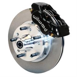
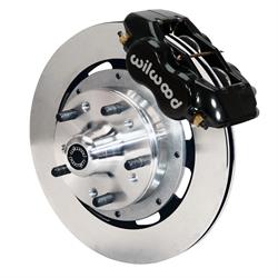
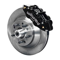
Recommended Brake Kits for G-Comp Series Front Suspensions:
- 91031958 - Speedway Deluxe Disc Brake Kit
- 83514010996 - Wilwood 11" GM Disc Brake Kit
- 8351407675 - Wilwood 12.19" GM Brake Kit
- 83514012271 - Wilwood 13" GM Disc Brake Kit Note: All disc brake kits made for GM A,F, and X-Body disc brake spindles will work with C-Gomp Series Kits
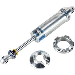
**Recommended Coil-Over Shocks and Springs for G-Comp Series Front Suspensions: **(2 of Each Required)
- 1061340CT - AFCO Street/Pro-Touring Coilover Shock (non-adjustable)
- 1063845PTCZ - AFCO Pro-Touring/Race Coilover Shock (single adjustable)
- 106284001CR - Afco 8" Chrome Coilover Spring To learn more about the entire G-Comp line of performance muscle car suspension parts, CLICK HERE.
Recommended Headers for G-Comp Series Front Suspensions
- 930-0105 G-Comp 1962-67 Chevy II/Nova Small Block Chevy Headers
- 930-0111 G-Comp 1962-67 Chevy II/Nova LS Engine Headers Notes
Brakes are offered in the 11", 12" or 13" diameter.
- 11" brakes will require a minimum of a 14" wheel
- 12" brakes will require a minimum of a 16" wheel
- 13" brakes will require a minimum of a 17" wheel
FAQ
Q: How many degrees of caster is this subframe setup for? What is the King Pin angle of the spindles? A: Suggested alignment settings for general street use are: 5 degrees positive caster 1/4 to 1/2 degree negative camber 0 to 1/8" toe in
Q: Is the G-Comp pro touring subframe painted or bare? A: These sub frames come bare steel, and can be painted or powder coated to your liking.
Q: Will a front sump oil pan on a LS series engine work with this clip? A: No you must run a rear sump oil pan.
Q: Can this suspension be used with a motor plate if the motor mount brackets are removed? A: This subframe is intended to use the side motor mounts but an experienced fabricator could certainly mount the engine with a motor plate if desired.