Universal Wiring Harness Instructions - Installation
One of the first steps that needed to be done in order to get our ‘68 Charger project road worthy, was to replace what was left of an old, hacked up wiring harness with a new one from Speedway Motors.
Again, the goal was to get our car drivable and do it on a budget. Therefore, it was a no brainer when choosing the right harness to get us there. We decided on the Speedway Economy 12 Circuit Wiring Harness due to its ease of installation. I truly believe anyone can install this harness with a little patience. It's affordable and above all else, it's dependable. Yes, we could have opted for the larger 22 circuit harness but the 12 circuit fit our needs for the time being, as we had not intended on using A/C or any other additional electric sourced options aside from electric fans up to this point.
The 12 circuit harness is great because every wire is labeled every few inches so you always know which wire is which. Another great feature of this wire harness is the easy-to-follow step-by-step instructions provided in the kit. Each wire is listed out specifically where it goes, why it’s necessary, and how to successfully connect it. There are handy diagrams for each area of the harness from the charging system, the gauges and instrumentation panel, and the headlights and tail lights. Being a universal kit, each diagram is also specific to your application, whether it may be Ford, Chevy, or Mopar. Most of the systems in the harness are designed for GM components such as the steering column, but nonetheless, we found it fairly simple to alter each connection to fit our classic Dodge.
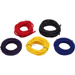
After ripping out the old harness and cleaning up the connections that were still usable, it was time to install the new harness. We found it useful to lay out the entire harness and route each separate area at a time. To start we routed all necessary wires to the rear of the car using the factory clips and trunk grommets. One important addition to note when installing any new wire harness is the incorporation of a wire loom or conduit. These keep the wires protected from heat damage or impact/abrasion damage as well as keep the install looking clean and professional. They are offered in various lengths and styles including plastic and fabric sheathing. Speedway Motors offers these protective conduits such as the Split Wire Loom Conduit Tubing, ¼ inch, and ¾ inch.
Using your typical wire strippers and cutters, we hand wired each connection to test the system before crimping and soldering on the new terminals. When it came to the taillights, and the headlights for that matter, we needed to splice into two wires on each side to accommodate the dual tail lights. These kits are designed with single light applications in mind, so we had to tap some extra wires into the system to complete the assembly.
For the headlights, it wasn’t as simple as splicing excess wire as the connections on our headlights are plug-in style. To remedy this issue, we simple sourced a dual headlight pigtail from the local salvage yard. Our particular pigtail came off a 1985 Oldsmobile Cutlass, which luckily for us, came with dual headlights. After a simple connection to the sourced pigtail, they plugged right in and were right at home in the Charger.
Next up was the area I was most concerned about, the gauges. Initially I intended to use the original instrument cluster, but after investigating their usability some it was evident that we would need to have them restored before reinstalling. It turns out that returning these gauges to original required more work and money than anticipated, and since I hadn’t planned on keeping them in the car when it comes time to overhaul the interior later on, I decided to alternatively build a new instrument panel using some custom cut stainless steel and aftermarket gauges to fit within. Once the new dash was in place, wiring to these new gauges was a breeze.
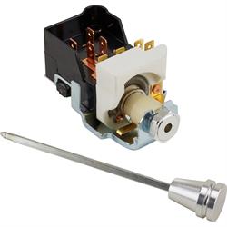
Additionally, I decided to wire in an all new ignition switch, headlight dimmer, and headlight switch rather than trying to utilize the original and worn out components. I wanted to include indicator lights for turn signals and hi/low beams without making additional holes in the stainless dash, and since the harness allowed for it, I fabricated my own indicator/headlight switch mount. This was simply cut down from an old steel table frame that conveniently had the correct diameter holes for the indicator lights as well as the 90 degree angle I was looking for to mount directly under the dash.
As for the steering column, our setup happened to be slightly different than what the instructions called for. To get around this issue, we simply did some quick researching and got a hold of the original wiring diagram for our car. After a couple minutes of tracing the correct wires to the new ones, it was a matter of minutes before we had the new harness successfully routed and connected to our steering column.
Another area of concern that turned out to not be difficult at all was the charging system. Our classic Mopar originally came equipped with a voltage regulator, ballast resistor, and breaker points system. As mentioned in a previous article, we swapped the OEM distributor for an aftermarket HEI type system with everything already built-in. The other upgrade we made was to the original alternator, by purchasing an aftermarket one-wire unit with internal regulator. This made hooking up our charging system easy, as we eliminated the original voltage regulator and resistor and were left with a clean and happily wired engine bay.
A neat feature of this kit is that the harness instructions include a troubleshooting guide, should you happen to have any issues after install. The only thing we came across after testing and final install were a couple loose connections, and one headlight brighter than the other. What we learned after addressing each of these issues was to check and recheck all connections to ensure a safe and secure circuit.
Additionally, and maybe a simple step that we totally overlooked, make sure you have good grounds where needed. Grounding your system can make all the difference when installing a new harness and is definitely one step that shouldn’t be bypassed. Another item to note is that when feeding wires through the firewall and any other metal barrier, it is important to have all corresponding grommets securely in place of these routing areas. Overtime, wires can fray and short-out due to constant vibration and friction against the metal body.
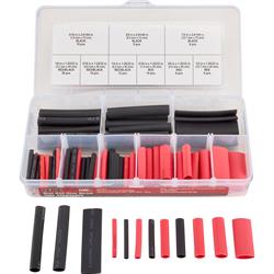
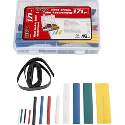
With the entire system test fit, all lights operating safely, and the car running smoothly, it was time to get our connections ready for final install. For this, you can use either an adhesive lined heat shrink butt crimps with a good crimping tool or you can solder the connection and slip over the heat shrink tubing insulation. Speedway Motors offers a couple great kits for doing so such as Titan Tools Dual Wall Heat Shrink Tubing Kit and Titan Tool Heat Shrink Tubing Kit. In either case, it is important to tug test the connections before shrinking them down. If the wire pulls out easily then the connection must be redone. Also be sure to slip the shrink tubing on prior to tying and soldering the wires. Once done properly, you will have a good strong and protected connection to last years to come.