Measuring Pinion Depth Using a Setup Tool
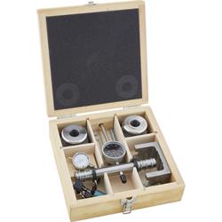
Over the years I have rebuilt several rear differentials, but have never used a pinion depth tool, such as the Professional Ring and Pinion Setup Tool Set that we offer here at Speedway Motors. I’ve had pretty good results using the contact pattern to adjust the pinion depth, however this time I wanted to see what this tool was all about.
I was helping a good friend out with the third member for his ’57 Chevy wagon. This particular third member came from a ’64 Impala and happened to have a factory posi unit with a 3.08 gear ratio. The car that this went into was slated to get a 700r4 trans, so we decided some 3.70 gears would make the car a lot more fun than the 3.08s would. He brought me a new set of Richmond gears and we got a Motive Gear rebuild kit.
I started by tearing apart the third member, getting it all cleaned up and prepped for the new parts. On these 55-64 GM rear third members I usually take the time to have a local machine shop shot blast the parts and then I paint them up just like they came from the factory. Here is the factory “P” case all cleaned up, painted, and ready to assemble.
With the ring gear and the factory shim installed I mocked up the setup tool. This tool is very universal and should fit in most rear end housings. You need to start by setting up the 2” travel dial indicator into the fixture that is supplied with the tool. It is important to take note that you set the tool to 1” of travel, however the centerline of the tool actually measures 2” from the tip of the indicator when it is resting in the fixture.
Next, install the “dog bone” onto the pinion gear, and hold it in place with the clamp provided with the tool. After that I put the races into the rear end caps and installed the assembly into the housing. The side bearing races need to be installed here and the springs apply pressure to the round adapters, which centers the entire assembly.
My initial measurement, with a .021” thick shim installed gave me a reading of 2.462”. The ring gear had a measurement of 2.476” etched on the face. The difference between the two is .014”, so I knew that by adding .014” to my initial shim thickness of .021” I would need a .035” thick shim under the pinion bearing. I took the assembly back apart and stacked a combination of thin shims until I got to .035” and reassembled. I ended up with a final measurement of about 2.4765” and decided that was close enough.
I went ahead and installed my crush sleeve, new pinion bearings and the new pinion seal then crushed the sleeve until I had 18in-lbs of preload. I measure this with a dial face inch pound torque wrench and I cover that in this article: https://www.speedwaymotors.com/tech/GM-10-Bolt-Rebuild After setting up the pinion gear with the shim that we know we want, I went ahead and measured everything one more time. It was spot on… 2.476”!
Now that the hard part is done, I reinstalled the carrier and set my backlash. This setup tool included a handy little mag base dial indicator that is perfect for getting on the tooth of the ring gear.
With everything done, I ran a quick contact pattern and got great results. The drive and coast patterns were right where they needed to be. You can even see on the drive pattern where the gears were lapped in at the factory… the same place my pattern is showing up!
Overall I really enjoyed using this new setup tool. You can certainly do the job without this tool, but it will take far longer and you never really know if your ring and pinion are going to run where the gear manufacturer intends them to. Every differential that I build will surely be set up with this tool from now on!