Installing a Custom Exhaust System: Part 2 - 1967 Chevelle
In our last installment, I was exhausted. I was uncertain whether or not a 3-inch diameter pipe could actually go where it belongs above the rearend housing.
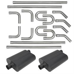
The best way to learn something is to try it. It appeared that the 180-degree U bend included in the DIY kit was pretty close to fitting the bill when coupled with two parts of a 45-degree bend to mate up to the muffler. Again, you don’t know until you try.
What I found after trying, was the U-bend was good, but it needed to have an offset to the IN/OUT so it would miss the trailing arms also packaged in the space above the rear end.
For that trick, I decided to split the U in the middle with an exhaust pipe cutter. Chosen because there was no clean way to clamp this in my chop saw.
I also noted that the U needed to open up slightly to angle the vertical pipes a bit more coming in and going out of the arch. For that I established the clocking needed when assembled and disc sanded a slight angle on both surfaces to be welded back together. This ensured that the mating ellipses were still identical and would mate with no gaps or irregularity. It really worked pretty slick. As you might expect, it was also very difficult to replicate for the other side when it came time to mirror my finished work.
I can say this now that I’m not laying under the car, it really wasn’t as difficult as I’d imagined it would be. The pieces are light they were easy to untack and readjust as needed. I was able to run the rear leg of the U-bend along the same path as the coilover. This helps ensure that there would be no contact with the spring through suspension travel.
Something else that was a critical concern that turned out to be a non-issue was clearance at full suspension compression. I could bottom the tires in the wheel houses before the pipe was even close to contact with anything.
The thing that I did not anticipate being as nerve racking as it was, were the tips where the exhaust became visible again. Once the pipe goes over the housing, there’s really only one place that it can go. At the corners of the fuel tank there is a clear path that takes you back out to the frame rail.
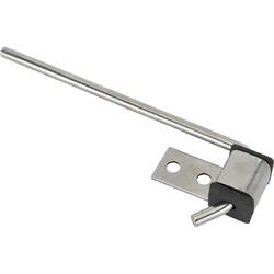
That’s where my final hanger location was drilled. I found a spot in the frame that had several pieces lapped and welded to make a fairly thick spot. Since the access to put a nut on the backside is very tight, I used that thick spot in the frame to drill and tap the bolt hole for this last hanger. When final assembly happens, this bolt will get also red thread locker to ensure it stays put.
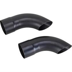
Back to those pesky exhaust tips. Originally I thought I wanted some sort of angle cut on them. That is until I made one and had it tacked in place. Hated it. I also tried to use a premade turn-down and ended up not liking the way it looked either.
In the end, I settled on a straight 90 degree cut at the end of the pipe. I’ll let you be the judge on whether or not I hit my mark. My goal was to tuck the system and have it appear as stock as possible from the side at ride height.
I won’t bore you with the details of repeating all of this on the passenger’s side. I will say that the headers are almost always different from side to side. You may also encounter some asymmetries in your floor and frame. I should also add, that the entire system was tack welded, then removed to be fully TIG welded and ground smooth by my buddy Gregg Scholl. I’m not worth a darn at welding upside-down anyway.