Steering Shaft and U-Joint Selection Guide
When to Start Designing Your Steering Shaft Routing?
The steering system is often designed late in the build process. In most cases it’s best to mock up the steering once the engine and exhaust components are installed, as well as finalizing steering column mounting angle and steering rack or steering gear mounting. Having everything in place will ensure you can spot any obstructions and properly design your steering shaft routing to clear said obstructions while still producing the proper joint angles to prevent steering bind. Steep angles and limited space may require a little trial and error to achieve the correct geometry, but with a little ingenuity and careful measuring, it can be accomplished.
How do I Determine The Spline Size of My Steering Components?
In addition to our application charts, you will need to determine the spline size on your steering components. Whether it’s a rack-and-pinion, steering column, or steering box, measure the outside diameter and count the number of splines. If it is a new part you can also often find these specs in the instructions or manufacturer's website. On some components there may be a flat spot or keyway on the shaft. In this case you can lay a straight edge across the top, or count half the diameter of the splines and double that number. We would then know how many teeth are in a theoretical full circle. Your final measurement should be something like "3/4-36", where 3/4 is the diameter of the shaft and 36 is the number of splines. This measurement will coincide with the U-joints we offer.
Speedway's Available U-joint Combinations:
- Smooth bore on both ends
- Smooth bore to splined or double D
- Splined and/or double D on each end
Is There a Maximum Angle That Steering U-Joints Can Handle?
If a single u-joint is installed we recommended not surpassing a 35 degree angle. This can cause hard spots or even lock up the steering or at the least premature wear on the joint bearings. If the u-joint angle exceeds 35 degrees consider a double jointed u-joint, which can take up to 70 degrees of angle.
A double jointed u-joint helps in applications where routing of the steering shaft(s) exceeds a safe 30-35 degrees. This is often seen with big block engine swaps or when the steering gear is mounted in a non-standard configuration.
What is a Steering Shaft Support and When Do I Use One?
Anytime the steering system has more than two universal joints installed, it is recommended to use a steering shaft support heim. It is best to install the support as close to the center joint as possible, or if one shaft is significantly longer than the other, it’s best to provide support to the longer shaft. Steering shaft supports are sometimes welded directly to the frame, but we offer a selection of mounting brackets with various angles and adjustment slots for a perfect bolt-in fit.
An adjustable steering shaft support heim like this is mandatory when using more than two U-joints in your steering shaft routing. It is also suggested for extremely long steering shafts to be used as a support for that shaft to prevent steering bind and unnecessary steering system harmonics.
When your steering system requires a support heim the preferred mounting solution is an adjustable rod end support bracket like the one shown here. This bracket is bolted to the frame and provides a mounting point for the heim. The adjustment slot and the threads on the heim body work together to provide the perfect mounting location to support your steering system.
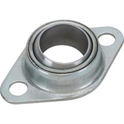
An additional support bearing option for some is this firewall mount flange bearing. This bolts to the firewall and supports a 3/4-inch diameter steering shaft. Some custom applications that use extremely short steering columns (kit cars like Cobra replicas for example) will need a bearing like this to support the steering shaft as it exits the firewall.
What Type of Steering Shaft should I Use?
You will find that steering gears and rack-and-pinion assemblies use a splined input shaft and that just about all aftermarket and most OE steering columns use a splined output shaft. Connecting these two major pieces of your steering system is the job of your steering u-joints and steering shaft. Depending upon the routing you may end up with one short length of steering shaft, or you may have two or more sections of shaft in your design. We offer three different styles of steering shaft and their use is solely dependent upon the u-joints you select. Speedy Tip: To strengthen the connection of a double D style joint to the shaft, you can drill a dimple on the steering shaft for the set screw to clamp to. Simply tighten the pinch bolt to make an indentation and drill 1/8-inch deep recess where the pinch bolt will tighten. A dab of Loc-Tite on the set screw is always good insurance before finishing.
Fully Machined Double D Shaft A fully machined double D shaft has two flats on the shaft its entire length that correspond to the female end of the u-joint. For example: the 3/4-inch measurement on a double D shaft is measured across the rounded portion of the shaft. The fully machined double D shaft is available in several lengths and can easily be cut to an exact length for your steering system. Note that the fully machined double D shaft can be inserted past the main body of the u-joint where it may come in contact with the joint and create binding, so always ensure the shaft is flush with the main body of the joint. Fully machined double D shaft is available in multiple lengths. After carefully measuring your steering system if you need an odd length it is best to go up in overall length when ordering and then make a finish cut to your exact length needed for your project.
Double D End Steering Shaft A variation of the fully machined double D shaft, this style only has the double D machined into each end. This provides a round steering shaft (to some more visually appealing) while allowing for a simple DIY installation of the double D-style U-joints at each end. A bonus to this design is the machined double D ends are designed to be inserted to the perfect depth into the U-joint with the round portion of the shaft fully seated against the U-joint body. There is no concern over exceeding the mounting depth and creating a bind with the joint. These steering shafts are available in lengths from 4- to 36-inches.
Solid Round Steering Shaft This is a solid steel 3/4-inch diameter round steering shaft that is used with a 3/4-inch "smooth bore" steering U-joint. Generally this application requires welding (some builders prefer the integrity of welding the joint versus a set screw) but there are instances where you could drill and pin the shaft, or grind a notch in it and use a pinch bolt configuration.
While both styles of double D steering shaft will work in a double D-style steering U-joint, you must use a smooth bore 3/4-inch ID steering U-joint for the solid round steering shaft. Like the fully machined double D shaft we mention above, the solid round steering shaft can be inserted too far into the joint as well and cause binding or steering lock. Ensure the shaft sits flush with the end of the main body of the steering U-Joint before beginning to weld the shaft and joint together.
Can I Use a Traditional "Rag Joint" When Building a Custom Steering System?
While we do offer several rag joints for OE GM columns, when it comes to aftermarket columns and designing your new steering system the typical OE rag joint with the proper connection specs is simply not made. However, that doesn't mean you have to live with steering system harmonics making their way to your steering wheel and into your hands. With the use of an inline steering damper you can easily subdue those harmonics and make your steering system feel that much more solid.
Determining the right steering system parts for your build, test fitting, and finalizing the steering system routing takes time, but doing it properly means you will have a safe steering system that will turn your steering wheel inputs into precise outputs at your front wheels while clearing any frame, engine, exhaust, or other hurdles along the way. Here at Speedway Motors we have everything you need to get the job done, just hit our steering shafts and joints section where you'll find the correct joints, steering shafts, adapters, and more to get you on the road quickly.
Updated by Mark Houlahan