Installing a Speedway Motors 22 Circuit Wiring Kit
Wiring seems to be a sticking point for a lot of builders. I know that I’ve removed my fair share of it with a pair of tin shears and a trash can after I dig into a new, unfinished project car. My choice for replacement of Scotch locks, wire nuts and glass fuse holders, daisy-chained together is either the Speedway Motors 12 circuit or 22 circuit wiring harness kit. The one you need depends on what kind of car you have. A bare bones hot rod seldom requires more than the 12 circuits provided in the base kit.
For this Chevelle project, I opted for the 22 circuit kit. Electrically speaking, a car gets complex very quickly when you add in complexities like electric fuel pumps, EFI, electric fans, stereo equipment, air conditioning, etc. That’s where Speedway Motors steps in. This kit is robust, allowing you to expand your system to suit the demands of the particular vehicle you’re installing it in. The detailed instructions and labels on every wire and component sub-package are impressive. A far cry from what came out of this car.
Whether you're using a 12 or 22-circuit kit, the biggest factor to a clean and easy installation starts with a good mounting location for the fuse box and the planning of where the main trunks of wiring will be routed. Once those things are sorted out and the panel is mounted, the rest comes down to pulling groups of wire and terminating connections. First, there are a few things to cover about automotive wiring in general.
Continuity – “In electronics, a continuity test is the checking of an electric circuit to see if current flows.” This is important to remember because in order for an electrical component to function, it needs to be part of a complete circuit. For instance, lighting circuits, like a gauge light, have a single 12v + wire connected to them. This is only half of the equation, though. That current needs to have a return path to the negative side of the battery as well. That’s where the next key term comes into play. Grounding. In the case of that little gauge light, the ground that completes the circuit happens through the contact of the bulb socket to the gauge housing, to the dash panel, to the body that the dash is attached to, to the chassis, to the battery. Can you now see why circuits often fail to work? In most cases, poor grounding is the culprit. A missing link between any of the components that are being grounded to will cause the circuit to fail.
Grounding – In a DC (direct current) system like automotive wiring, the grounding of each circuit is critical in providing a complete path back to the negative battery terminal. Again, without a complete loop of current, you have no circuit.
Relays – Relays can be a mysterious widget when you’re starting into the wiring world. Needlessly so, in most cases. A relay is simply an electromagnetic switching device that prevents a high-demand component from overloading the switch that the user controls the component with. A relay can typically be triggered with either a positive or negative input signal.
In the simplified diagram shown here, you’ll see that the high current circuit is able to be isolated from the low current switching circuit. This effectively allows heavy gauge wire and contacts to handle the current and amp load while allowing your toggle switch or the like. It’s important to remember your switch merely controls the relay. The relay controls your fuel pump, fans or horn.
There are two separate circuits at work inside a relay. The one attached to your switch completes a circuit that energizes a small electromagnet. When that electromagnet is energized (by providing it either a ground or positive signal with your switch) that magnet pulls in a contact, which completes the other high current circuit that actually powers the component.
Example: In the case of a thermostatically controlled engine fan, your temperature sender will provide a ground at a set temperature. When this happens the relay that controls the fan should have 12v provided. One input will attach to a 12v source from the ignition switch, this is your low current input. The other 12v input should be a heavier gauge, fused wire that provides the power to the fan. The ground terminal on the relay will connect to your temperature operated switch, which can also have a toggle installed that will provide a ground on demand. On the output side, the heavy gauge power supply wire coming off the relay connects to the pos wire on the fan. The fan is grounded to the chassis, where hopefully your battery is well grounded.
When the low current circuit on the relay is completed by the engine temp switch going to ground, the fan kicks on with power provided by the activated high current circuit. When the temperature drops and the sender opens the circuit again by taking away the ground path, the fan stops until the relay is grounded again.
Once you’ve got a working understanding of relays, automotive wiring becomes much less intimidating. Your hot rod also becomes much safer. Now, let’s get back to wiring this Chevelle.
This location on the firewall was good enough for GM so I guess it’s good enough for me, too. The fuse blocks in this era were originally equipped with glass fuses and a very limited array of circuits.
I mounted my fuse block via existing holes in the firewall. I used two long ¼” Allen bolts. On the engine side of the firewall I opted to use a Seals-It molded rubber and aluminum double grommet in place of the original GM square bulkhead plugs to transfer wires from interior to engine bay.
Once you’ve got the fuse block mounted, you can start pulling bundles of wire where you want them. In my case, there were four distinct bundles.
- ENGINE
- FRONT BODY (lighting)
- REAR BODY (lighting)
- DASH
For the most part, these bundles are already grouped together pretty well. There were a few wires I pulled from one to another because I made a distinct and immediate separation of the wires that passed through the firewall. I wanted to run as much of the wiring in the engine bay as I could, above the inner fender well and inside the left front fender. Leaving only the few wires that go to the engine and starter, I routed in the factory gutter above the distributor. I wanted to keep a somewhat factory appearance, but without all the clutter.
From there, you’ll continue to make finer distinctions on where you need wires routed and pulled out of the main bundles.
I preferred to route my rear lighting harness as the factory had it. Originally, this task was handled by a stiff copper and nylon ribbon cable that runs in a channel in the floor. I mimicked this routing and connected the harness to a reproduction of the rear lighting harness to keep a factory appearance, sockets and cloth tape wrapping.
That brings me to another neat little trick I’ve discovered for keeping wires in place and protected. Scraps of peel & stick insulation, in this case BoomMat. I used strips to secure the wires in place near the fuse block and in the floor gutter.
Once you’ve got your wiring kit to this stage, you’ll find that the instruction diagrams provided with the kit are very detailed and informative. It’s all just termination of wires from this point.
On that topic, I’ll leave you with one last trick little item that I’ve recently started to use and used extensively through out this project. Heat seal and solder terminals. These are a really great way to create an honest to goodness soldered connection that’s tidy, weathertight and strong. I dip the bare wire into paste flux to ensure good absorption of the solder into the wire for a sure connection.
In keeping with my desire to have a stock appearing installation, I retained all of the old plugs and sockets along with a fair amount of the original wiring attached to them. These pigtails help make a universal kit look like they were tailor made for your vehicle. These can also be sourced from your local pick-a-part salvage yard as well.
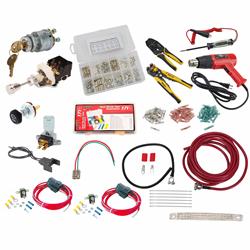
After tackling this latest wiring project, I assembled some kits that pull together, from what I felt to be the MVP’s of automotive wiring. These kits will help complete and ease your installation.